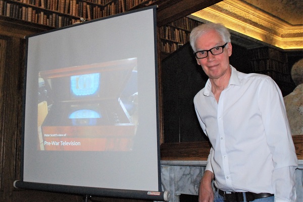
Peter Scott has a long-standing interest in the history of television and gave a great talk to 22 LRS members & friends at the BHH on 25th January 2023.
See also his personal Nostalgiatech website: http://www.nostalgiatech.co.uk/
Bio: Peter did an Engineering Apprenticeship with Ferranti followed by an Electrical Engineering degree at Heriot-Watt University, where he graduated in 1972. He was then pleased to be offered a job as an R&D engineer with Hewlett-Packard (HP) at South Queensferry, where he remained until he retired in 2004.
=====================================================================

1. Good evening!
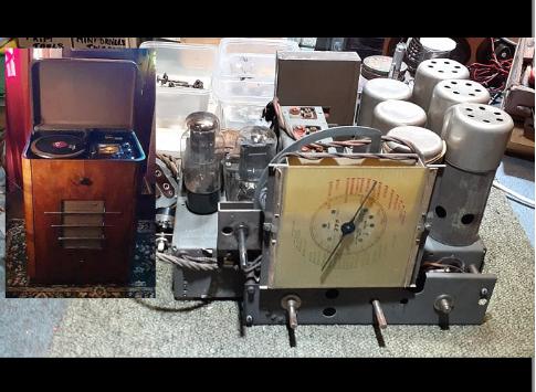
2. GEC chassis under floor. I was excited by the 3 gang tuner! Various radios were bought at jumble sales. Various TV sets were repaired for friends and neighbours.
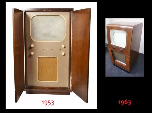
3. My father bought a Philips projection set in 1953. Then 10 years later a school friend gave me a small 10″ console set that was dead. I struggled with this and then took advice from our local radio shop who told me it was a TRF with tuning fixed on Channel 1, but they kindly gave me two 17″ sets from their junk pile – an Ekco T231 and a Pye VT7. I got both of these working and we used the Ekco as the family set as it gave both BBC and ITV. My father then removed the innards of the Philips projection set and turned it into a stand-alone cupboard!
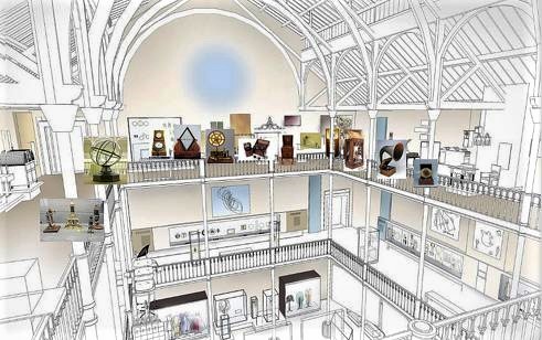
3. Excited by the Royal Scottish Museum science gallery – Orrery, Microscopes, telegraph equipment, Early Phones, Crystal sets, Phonographs, Gramophones, EMG, Voigt Corner Horn, Emitron camera tubes, HMV 901 receiver – early 1930s technology.
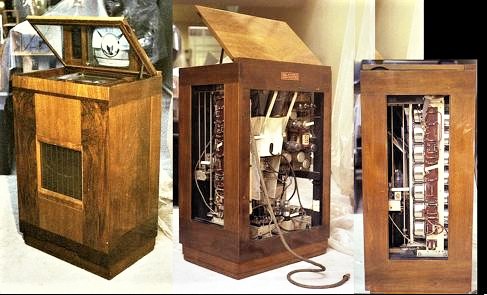
4. Island case. Side and rear panels open to see all the works. Vertical CRT with shallow deflection angle. Vision Rx TRF 45MHz 6 stage. Aerial cable with two layers of braiding and gutta percha. Large aerial cable and plug.
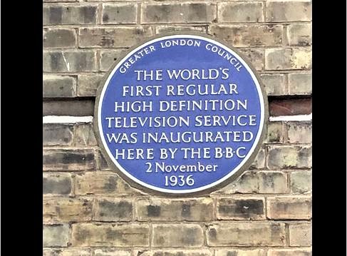
5. This is the blue plaque mounted on the wall of Alexandra Palace marking the official start of BBC Television on the 2nd of November 1936..
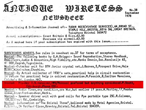
6. Married life. Holidays in Bath & Bristol. Tudor Rees shop & News letter. Placed wanted ad. Some TVs contained radiograms. I wanted a set with no other function than TV Prefer EMI (HMV or Marconiphone). 2 replies.

7. One reply from a person also seeking a pre-war set. One reply offering a HMV901 in Cornwall wanted £120. Set off in Reliant Rebel that cost £75 pounds (less than the TV)! Bought the HMV901, drove it to Edinburgh on double airbed.
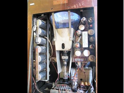
8. Lots of leaky capacitors were replaced before seeing first light. Lots of white flecks indicating EHT transformer breakdown.
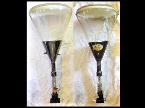
8A. The cathode ray tubes for these sets were made from Pyrex glass, so they were not quite as fragile as they looked. Early ones had a blown envelope but to improve the optics of the screen later ones had a separate moulded face plate.
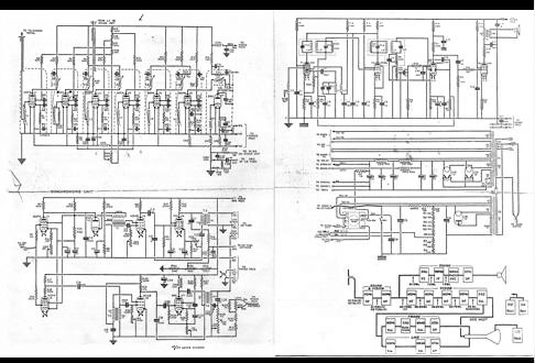
9. 45MHz vision TRF. 41.5MHz sound tapped off second stage then superhet 1.5MHz IF. Timebases for 405 interlaced & 240 progressive. Mains derived EHT.
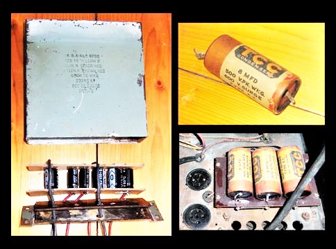
10. Multiple electrolytic cans stuffed with modern capacitors.
Toilet-roll copies of original TCC electrolytic capacitors.
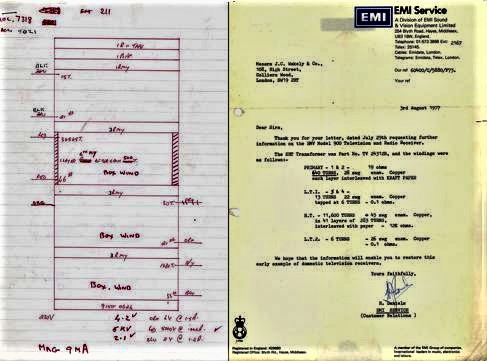
11. I had to replace the shorting EHT transformer. The first pass had breakdown between windings and the core. I suggested PTFE covered wire for the heater winding. Ten years later I got a copy of the EMI winding details with EHT 11,000 turns. For my transformer I used 36,000 turns.
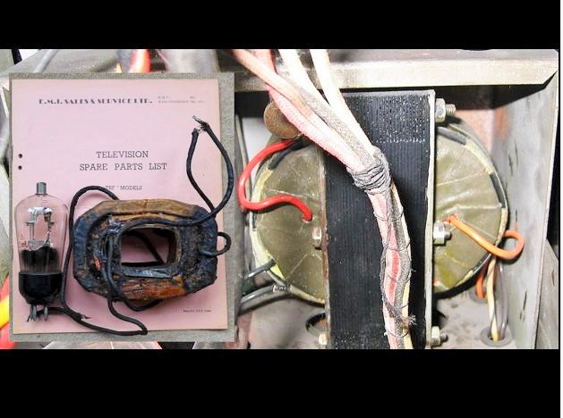
12. LHS – Original winding.
RHS – Original core rewound in 1979 and still giving good service.
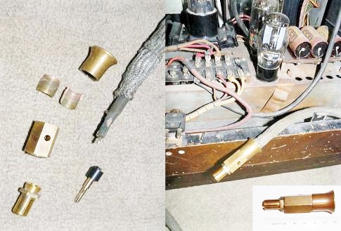
13. My set came with the original double-braided aerial cable but no plug.
A very skilled fellow enthusiast made a run of replica plugs.
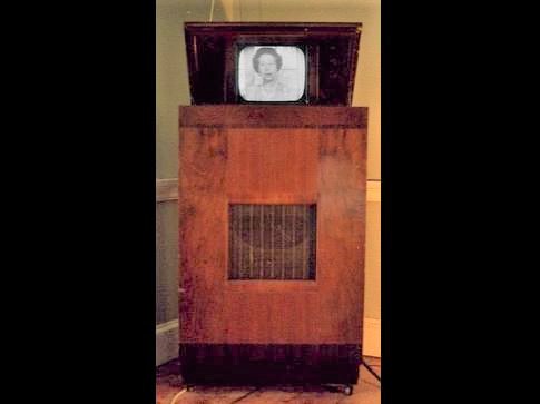
14. This is the Queen giving her final 405-line Christmas message in Dec 1984.
I had to make a frequency converter to receive the Channel 3 transmission on 56MHz on my Channel 1 (45MHz) receiver.
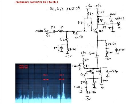
15. My frequency converter circuit.
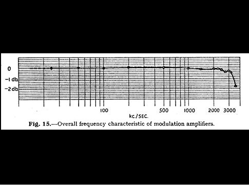
16. The bandwidth of the Alexandra Palace transmitter was pretty flat all the way up to 3MHz.
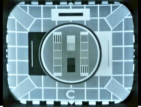
17. The test-card shows the resolution of the finest (3MHz) bars is good.
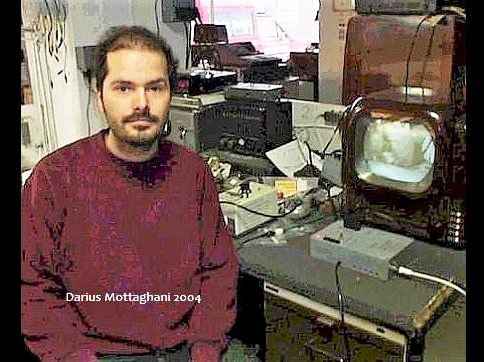
18. When BBC and ITA started transmitting on UHF 625 lines colour they continued to maintain the B&W VHF 405 transmissions by converting the 625 to 405. The standards convertors were complex and required a full 6 foot high rack of equipment. After the 405 line broadcasts were terminated in early 1985 a small number of enthusiasts designed their own standards convertors. In 2004 Darius Mottaghani designed a very clever convertor using charge coupled delay lines and this could be contained in a small box as is shown here.
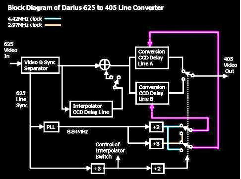
19. Block diagram of Darius Mottaghani’s standards converter.
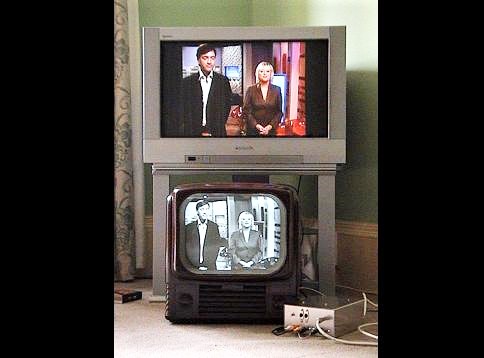
20. The BBC & ITV continued to transmit both the 405-line B&W and the new 625-line colour service by using their standards convertors.
The photo above shows a 625 line broadcast converted by the standards converter that I built based on Darius’ design and displayed on a post war 405 line set.
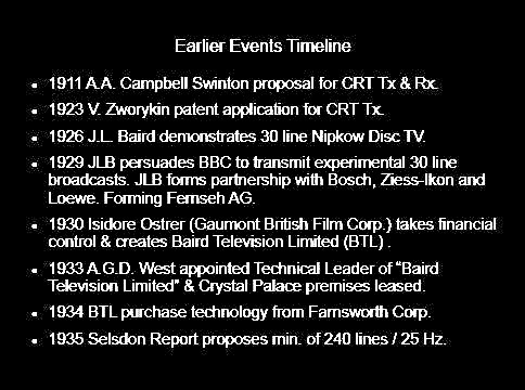
21. Earlier Events Timeline.

21. Selsdon Committee Timeline.
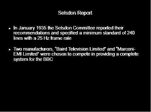
23. Selsdon Report : Minimum 240 lines 25Hz.
Only Baird Television Ltd & Marconi EMI to provide complete system for the BBC.
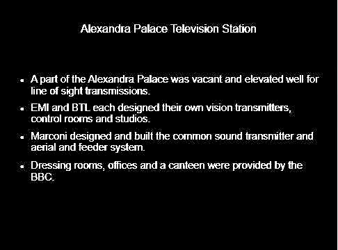
24. The Alexandra Palace television station.
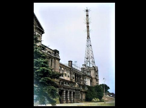
25. The south east corner of Alexandra Palace provided the accommodation for two studios with control rooms and transmitters.
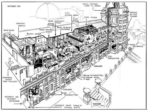
26. Alexandra Palace: first floor Baird studio in foreground and the EMI studio towards the tower and control rooms in between. Ground floor Marconi sound transmitter. Baird vision transmitter on one side and EMI vision transmitter on the other.
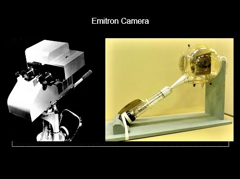
28. While Television receiver technology was largely standardised on the cathode ray tube at this time, designing an effective camera was more difficult and when it was created RCA & EMI patents restricted the methods of other developers.
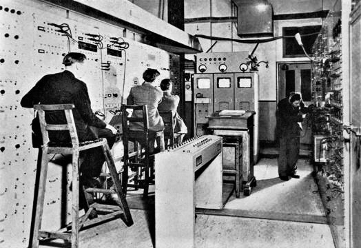
29. In the Alexandra Palace Control Room the engineers on the graded height stools are adjusting out the imperfections in the pictures. Camera signals consisted of scanning, focus and shading adjustment for Tilt & Bend control. This was followed by camera selection/fading and also delay adjustment for seamless switching between cameras with differing remote cabling. After the B and C amplifiers the inverted video signals were gated to remove the spurious flyback signal content. Then correct line and frame synchronising signals were added before the videos signals were passed to the monitors and transmitter.”
The producer was located on a balcony above the area in this photo. It was accessed by a steel vertical ladder.
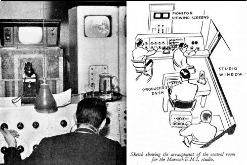
30. At his level the producer can see directly into the studio through the window on the right and can give instructions to the studio staff regarding camera angles and positions etc and he can check what is actually being broadcast and what camera signal will be chosen next.
In front of the producer sat the sound mixers and behind him the vision mixer .
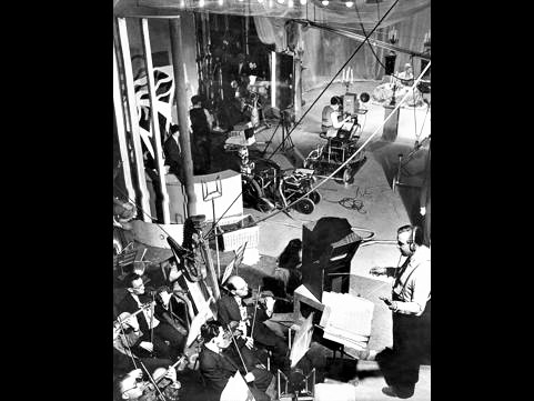
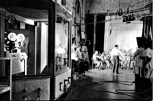
31. Producer’s view from the control gallery window.
As well as the camera directly addressing the action a second camera offers a different view on the left and a third one perhaps used for captions and announcements.
Boom microphones are positioned above the subject and the orchestra.
A bridge carries lights above the scene.
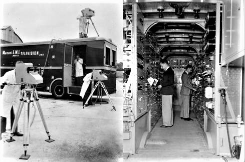
32. In addition to the cameras and control room within the building a mobile control room and cameras permitted televising of many different events around London with signals transported by a ring of cabling and also radio links from an extending aerial at the remote site.
35. Click on link below to view BBC demonstration film that was made in 1946. The equipment is largely the same as in the pre-war era.
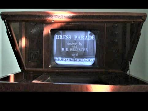
36. In 1937 a demonstration film showed examples of the types of programs that were being broadcast. The film was transmitted outwith normal hours to permit receivers to be demonstrated to potential customers.
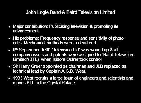
37. Summary of Baird developments.
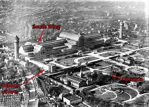
40. Baird research labs, offices and TV studios were in the basement of the South Wing. The South Tower acted as an aerial tower. The School of Arts was used for the manufacture of receivers.
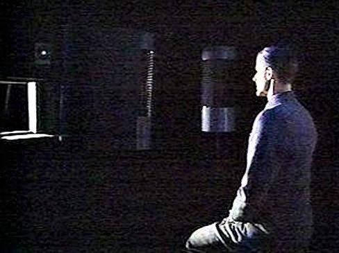
43. The principal stumbling block for television in the 1920s and early 1930s was the lack of a viable camera. Dating from the 30 line era the best “camera” that J.L.Baird could come up with was the spotlight scanner. This was very limiting, requiring performers to conduct their act in total darkness whilst directly facing an intense scanning beam.
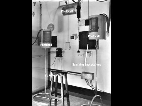
44. Whilst the subject sat in front of the scanning beam the light reflected off them was sensed by a set of photo cells. In terms of the television image these photo cells were the equivalent of stage lights on a conventional film set. Moving them in any direction gave the same effect as moving the lights.
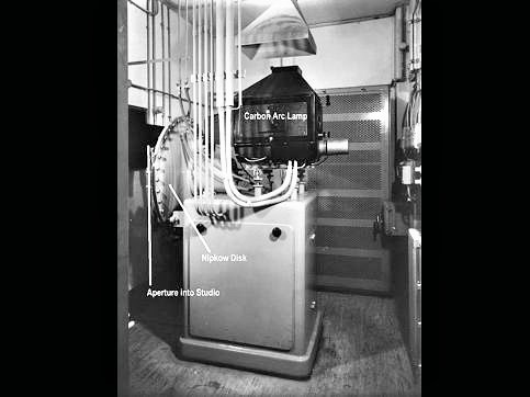
45. The scanning beam came from an arc lamp whose beam was passed through a Nipkow disc run in a vacuum at 6000 rpm. This was hot and noisy and needed to be located in a separate room.
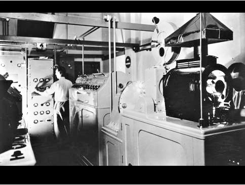
46. The one area where Baird’s system performed well was in televising films. The scanning light was similar to that used in the spotlight studio except that the holes in the scanning disc were arranged in a circle rather than in a spiral because the frame scanning was achieved by the linear transport of the film.
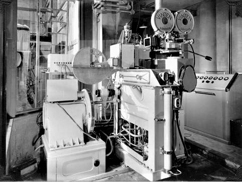
46. To achieve a more versatile television camera a further extension of the film scanner was created. This equipment was the 17.5mm Intermediate Film Camera. (35 mm film cut in half for cost saving.) Scanning was as per the film scanner but in this case the film was still wet having been rapidly developed after passing through a conventional cinema film camera. The reels only held 1000ft of film giving no more than 20 minutes of program before the non-trivial process of reloading with film had to take place.
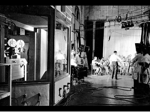
48. The Baird film camera could pan sideways but was always tied to the massive developing tanks and scanner. And as with the other disc scanners it was noisy and had to be isolated in a sound-proof box.
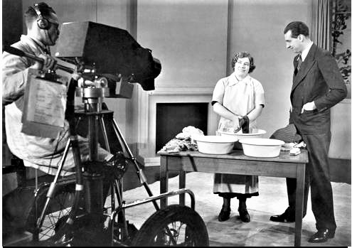
49. Baird was well aware of the impracticality of the spotlight and intermediate film camera systems and decided to purchase technology from the Farnsworth company in the US. Farnsworth’s image dissector camera suffered from poor sensitivity and geometry distortions and was seldom used in practice during the Selsdon trial period.
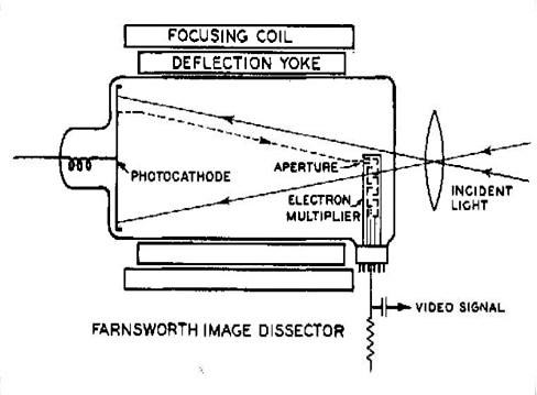
49A. Schematic of the Farnsworth Image Dissector camera tube.
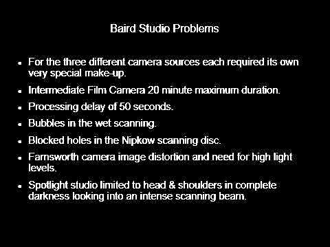
50. Summary of Baird studio problems.
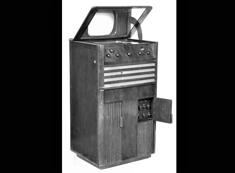
51. The Farnsworth camera technology was not a success but Baird definitely benefited from the receiver CRT instruction on phosphor recipe and electron guns. The 15” screen size was suggested by Farnsworth and was an advantage over the competitors who had generally limited themselves to 12” displays.
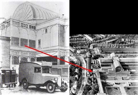
52. As I understand it the initial production of receivers was all done at the Crystal Palace site.
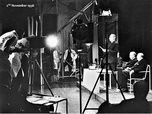
54. At the official opening of the BBC Television Service on 2nd November 1936 a coin was tossed to determine whether the Baird or EMI system was to be used first. Baird won and used the Intermediate Film camera but as in this photo the Farnsworth camera was present as a back-up.
55. Announcements were made in the Spotlight Studio and the ceremony took place in the Baird Studio. The ceremony was then repeated using the EMI studio.
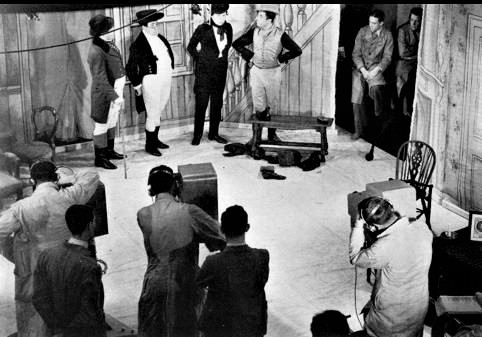
56. The difference between the Baird and EMI systems was truly like night and day. With the EMI multiple camera angles and a single system that could be used inside a studio or outside.
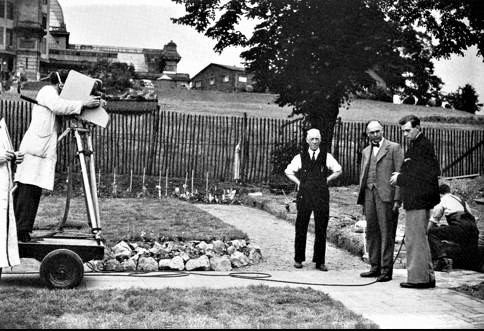
57. EMI cameras were light-weight, silent and useable outside as well as in the studio.
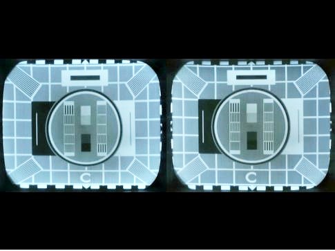
58. Comparing the 240 lines (L) and 405 lines (R) images the difference was not dramatic but what you don’t see in a static image is the flicker with 240 lines.
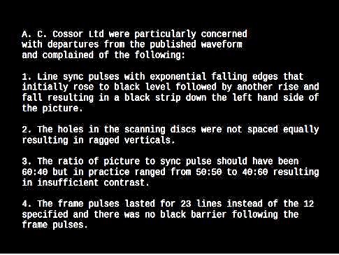
60. And if flicker wasn’t bad enough, Baird equipment did not conform to a stable specification.
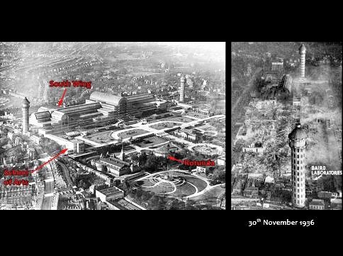
61. So the BBC Television Service started on the 2nd of November 1936 but unfortunately for Baird the Crystal Palace caught fire on the 30th. This destroyed the BTL offices, labs and experimental studios. They still had the equipment that was installed at Alexandra Palace and they still had the production facilities for the manufacture of receivers although this was later farmed out to Bush Radio to liberate space at the Crystal Palace site.
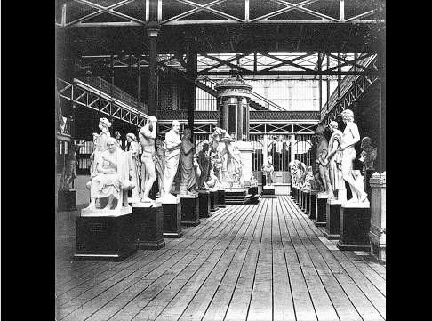
62. You might wonder about the Crystal Palace fire – was it an insurance job because BTL could see the writing on the wall?
No, the fire started a long distance away from BTL’s part of the building. The fire spread rapidly because the floors were wooden and coated with pitch on the underside. They also had gaps between the boards for ventilation. And there was a strong wind from the north at the time of the fire..
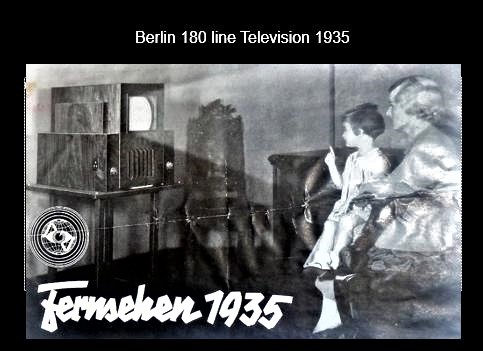
64. Was this the world’s first regular high definition studio and transmitter in London in 1936? That depends on how you define high definition. In Germany a year earlier 180 line transmissions were broadcast from the radio tower in Berlin but there were no receivers available for the general public to buy. Receivers could only be seen in public viewing rooms.
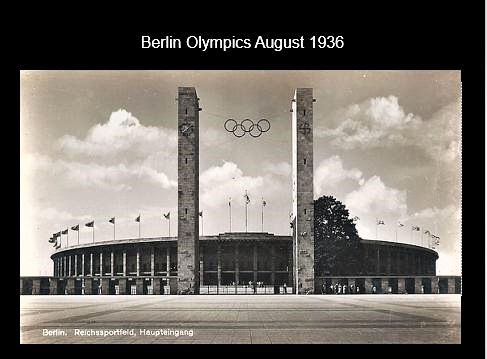
65. In August 1936 the Berlin Olympics were held and televised with their
180 line system.
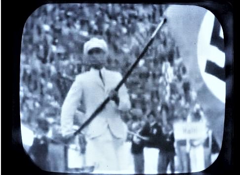
66. If you didn’t mind the Nazi propaganda the 180 line television picture wasn’t too bad except that it flickered just like that of Baird.
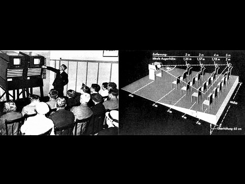
67. The 180 line display was probably quite acceptable given the relatively small screen size of the receivers in the German viewing rooms, but there were no receivers available for individuals to buy.
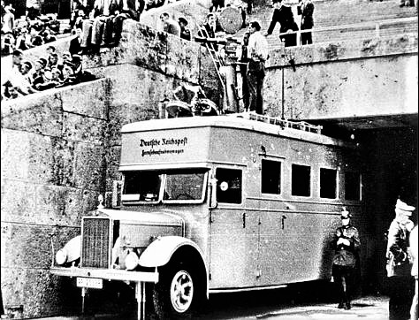
68. The most important use of the 180 line transmissions was for televising the Berlin Olympic Games in August 1936. Fernseh AG, the conglomerate that Baird had previously been a part of, used an intermediate film camera with developing and scanning equipment contained in the van below the camera.
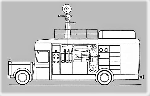
69. Schematic of the film camera / processing van.
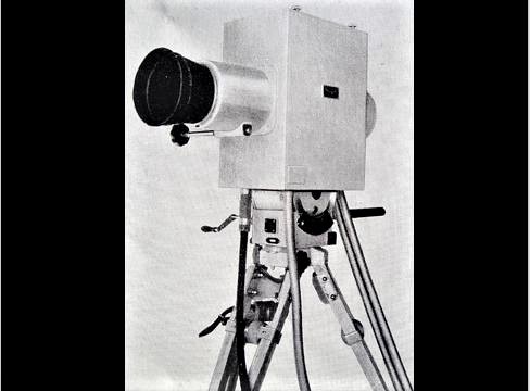
70. and like Baird, Fernseh also used a Farnsworth type camera.
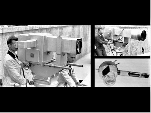
71. The limitations of Intermediate Film Transmission and Farnsworth scanning were obvious and there must have been some relaxation of the “purely German” technology requirement because Telefunken bought the manufacturing rights to RCA Iconoscope design
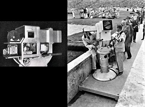
72. Two of these Telefunken cameras were built and located at the track side of the Olympic stadium. Although they would have been capable of higher line rates the distribution and transmitting system was built for 180 lines so these cameras were also run at that line rate.
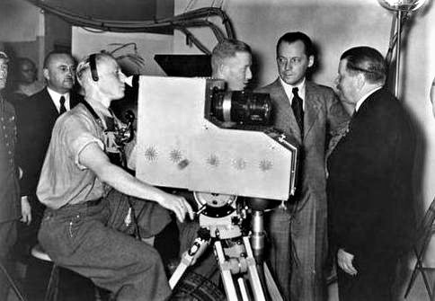
73. The German Post Office were also interested in television and they too created an Iconoscope camera that was located at the swimming pool for the duration of the games.
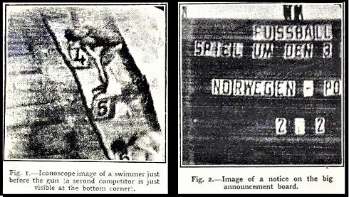
74. Reporting in the (British) Wireless World magazine in August 21st their correspondent was rather less than impressed with initial television coverage, the clarity being insufficient and the projection receivers being unreliable. The images from the iconoscope cameras were shadowy and distorted in the dull weather conditions. Those from the intermediate film camera were reported as quite clear and contrasty but accompanied by badly distorted sound, noting that its recording on the film suffered from the rapid development process.
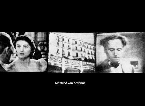
75. Manfred von Ardenne, a leading German TV experimenter, commented that:
“The quality of the “direct” television transmissions improved during the early stages of the Games almost from day to day, so that by about the middle of the Games, thanks to the accumulated experience in practical transmission technique, quite a useful picture quality was attained – not quite up to the standard of ordinary film transmissions but noticeably approaching this.
The on screen photos in von Ardenne’s book probably give a fairer impression of the 180 line broadcasts than the Wireless World prints.
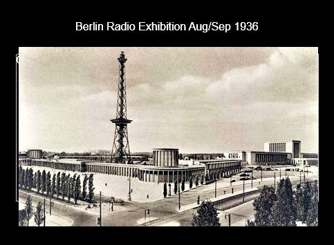
76. Just after the Olympics the Berlin Radio Exhibition opened.
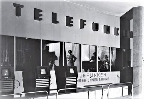
77. The Berlin Radio Exhibition displayed a variety of both 180 line / 25Hz non-interlaced and 375 line / 50Hz interlaced receivers and Telefunken displayed the massive Olympia iconoscope camera alongside a much more portable 375 line camera that was also shown in a demonstration studio. The 375 line receivers looked very similar to the earlier 180 line versions.
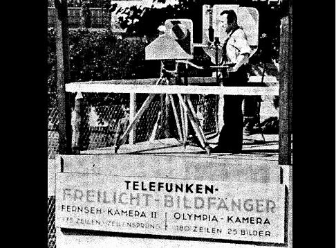
78. Telefunken displayed both the 180 line Olympic camera and their new much smaller 375 line camera at the Berlin Radio Exhibition.

80. The reasoning behind the choice of 180-line scanning.
81. Coincident with the Berlin show, Radiolympia was running in London.
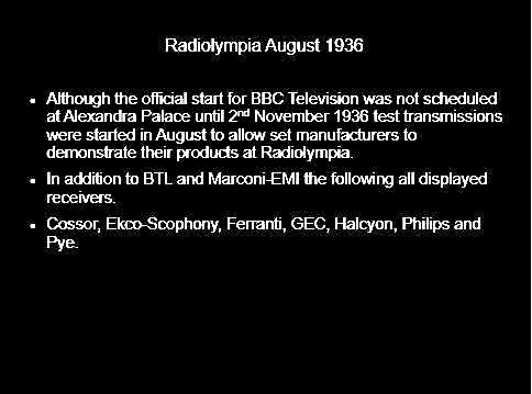
82. Before the official start of BBC Television in November 1936, the annual Radiolympia exhibition in London ran in August.
83. Peter’s Nostalgia website.

Questions?
Many thanks Peter for a great talk.
=============================================================
